Converting a raster image into a vector image in CorelDraw. Corel Draw lessons. Bevel effect. Adding volume to our forms How to create a painting effect in coreldraw 8
Date of publication: 02.11.2012
Does drawing a portrait without the skills of an artist or having never had an art education behind you seem very difficult? In this lesson we will look at how you can do without long training with good results. We will draw a portrait from a photograph, simplifying complex details, creating layers to make our work easier.
Let's say right away that the first pancake will most likely be lumpy.
1. Photography
2. Let's start with the face
3. Select a sample
4. Light and dark
5. Draw facial features
6. Adding Highlights
7. Let's get down to details
8. Draw the eyes
9. Check with the original
10. Draw the mouth
11. Hair. Let's start with color
12. Lighter now
13. Wear a T-shirt
14. Maximum effect
15. Adjusting contrast
Portrait in CorelDraw - final result
Photo
1.1 Find the photo we need and open it in a new CorelDraw document (File > New > Import > file name)

rice. 1.1 Selecting a photo
1.2 Make a bookmark in the right menu (Window > Dockers > Object Manager)
1.3 Create a new layer in this menu (New Layer) and name it, for example, “pic”
1.4 Block our object (in the right menu, click on the small pencil icon)
Let's start with the face
2.1 Create the next layer on which to draw the face.
2.2 Let's call this layer “face”
2.3 Using the Freehand Tool, we begin to repeat the features of the face, neck and body.

rice. 2.3 Freehand Tool
2.4 It is best to use thin lines, say hairline thickness. This can be configured in the panel below the top menu.

rice. 2.4 Contour of face, neck and body
Choosing a sample
3.1 After drawing most of the lines of the face, you need to select the main skin tone from the imported image. Tool - Eyedropper Tool

rice. 3.1 Eyedropper Tool
3.2 Click on the picture until we select a color that we like and which can be used as the main skin tone.
3.3 Fill the drawn outline with the selected color.

rice. 3.3 Face fill
Light and dark
4.1 Now you can start creating a palette of skin tones. Choose a shade in the picture that is darker than the main one. These will be darkened areas of the skin. In the same way, you need to choose a color for the illuminated areas.
rice. 4.1 Dark areas of the face
Drawing facial features
5.1 Using a darker shade, we continue to draw the darkened areas of the face with the Freehand Tool (see section 2.3.). Let's name the layers Shadow dark and Shadow light

rice. 5.1 Contour of dark areas of the face
5.2 Add darker colors to the palette and work on the darkest areas, after which we move on to the details.
Adding Highlights
6.1 Having finished with the shadows, we move on to the light areas. Perhaps the easiest way here is to hide the layers with shadows on the face so that you can better see the original in the photo. To hide layers, click on the small eye in the left toolbar (where we create layers) next to each of them.

rice. 6.1 Light areas of the face
6.2. In order to get realistic, delicate light areas, you can not select colors by searching, but use a white fill and experiment with the transparency of the Interactive Transparency Tool

rice. 6.2 Experiment with transparency
Let's get down to details
7.1 Let's get down to the small details: let's start with the nose and eyebrows. At this stage, the face gradually becomes more realistic and closer to what we want to see.

rice. 7.1 Eyebrows and nose
7.2 Create each part of the face (eyebrows or nose) in different layers and, after they are completely finalized, fix them in the right toolbar with a “small pencil”.

rice. 7.2 Toolbar "small pencil"
Drawing the eyes
8.1 Draw the main elements of the eye, such as eyelashes, eye contour, pupil and iris, and fill them with colors.

rice. 8.1 Drawing the eye
8.2 The color of the white of the eye should not be bright white, so that it does not catch the eye, let’s make it pale grayish.

rice. 8.2 Darkening the eye
8.3 To give your eyes shine, colors need to be selected very carefully, studying them in the photograph. It is also necessary to determine in advance which details need to be slightly exaggerated compared to the original.

rice. 8.3 Simplification of elements
8.4 The brightest detail of the eye will be a small highlight on the pupil.

rice. 8.4 Glare on the pupil
Checking with the original
9.1 Now copy the photo, having previously unlocked it, and paste the copy on the side of our illustration. This will help you adjust all the shades of colors so that they combine most successfully and harmoniously with each other. This can be done most productively by comparing a separate photograph and a drawing.

rice. 9.1 Comparison of drawing and photo
Drawing a mouth
10.1 Work on the mouth begins with its main outline drawn with the Freehand Tool and filled with a suitable slightly pinkish color.

rice. 10.1 Drawing the outline of the mouth
10.2 Add an intermediate shade of dark color for the upper lip and about two shades lighter for the lower lip.

rice. 10.2 Arrangement of shadows on the lips
10.3 Draw the darkest stripe, the one where the lips meet.

rice. 10.3 Dark line on lips
10.4 Create a highlight on the lips in the same way as we painted the eye. Let's add a little transparency to it using the Interactive Transparency Tool in the left toolbar.

rice. 10.4 Interactive Transparency Tool
Hair. Let's start with color
11.1 Hair should also be painted on a separate layer. We create their main outline with the Freehand Tool, without going into too much detail, and paint them with a gradient or a regular tone. This will be the main hair color.

rice. 11.1 General hair contour
11.2 Draw small curls separately from the main body of hair (also with the Freehand Tool.)

rice. 11.2 Small hair details
It's lighter now
12.1 Now use the Freehand Tool to draw lighter areas on the hair and fill them with a light brown tone.

rice. 12.1 Light parts of hair
Wear a T-shirt
13.1 Let's determine the main colors of the T-shirt. In our case, these will be different shades of blue.

rice. 13.1 Drawing the outline of a T-shirt
13.2 Draw folds on the T-shirt. They also need to be drawn with the Freehand Tool. First dark, then light. It’s better not to overuse details, since our main task is to focus all the viewer’s attention on the face.

rice. 13.2 Folds on the shirt
Maximum effect
14.1 Everything is fine, but a little work on the details to achieve maximum effect will not go amiss. Select the main object in the group of face objects and, using linear transparency, use the Interactive Transparency Tool to change its sharp edges to vanishing ones.

rice. 14.1 Interactive Transparency Tool
14.2 Change the direction so that the transparency is as smooth as possible.

rice. 14.2 Working with transparency
Adjusting the contrast
15.1 Apply the same shadows with soft transitions to other areas of the skin.

rice. 15.1 Adjusting transparency
15.2 Looking at the illustration as a whole, we see what points we need to improve.
15.3 Add a background, whichever you like best.

rice. 15.3 Finishing work with the background
15.4 The main rule is that everything should always be in moderation.
The Blend transition function allows you to transition between two objects, creating a single whole from them. Extrude allows you to create 3D objects by extruding planes and surfaces from a selected object. Contour makes it possible to create copies of an object whose outline follows the shape of the original object.
Share your work on social networks
If this work does not suit you, at the bottom of the page there is a list of similar works. You can also use the search button
Topic: Applying special effects to objects CorelDraw
Purpose of the lesson: study the types and methods of applying special effects to objects CorelDraw.
Type: learning new knowledge.
Equipment: computer, projector, board.
Plan
- Organizational moment 3 min.
- Learning new material 35 min.
- Consolidation of new material 5 min.
- Homework 2 min.
2. Learning new material
Effects in COREL DRAW
The term special effects - serves to denote a very broad concept. CorelDraw special effects allow you to automate your work and simplify the process of creating complex images.
- Perspective (Perspective) - allows you to apply one- and two-point perspective to an object. In this case, you can create the impression that objects are at some distance. To do this, you just need to drag the nodes on the dotted border.
- Shell (Envelope) - allows you to deform an object by dragging nodes on the bounding box.
- Transition function(Blend) makes it possible to transition between two objects, creating a single whole from them. This feature can also be used to create spray and shading effects.
- Extrusion (Extrude) - allows you to create three-dimensional objects by extruding planes and surfaces from the selected object.
- Circuit (Contour) - makes it possible to create copies of an object, the outline of which repeats the shape of the original object. Moreover, copies can be located both inside the original object and outside. This is another way to create shadows, gradients, frames, and many other interesting effects.
- PowerClip - an extremely useful feature that allows you to cut holes inside some objects in the shape of other objects.
- Lens (Lens) - makes it possible to apply special effects to certain areas of the image.
Perspective
With this effect, you can add perspective to an object to create the impression that it is at some distance, or vice versa, that it is moving towards the viewer. As a result of applying this effect, the image becomes three-dimensional.
When you add perspective to an object, a dotted frame with four nodes appears around it. You can drag these nodes to move the object's vanishing point. Vanishing point - This is a point in the foreground or background of an object, towards which the size of the object gradually decreases (in the limit, it turns into a point on the horizon).
You can apply one- or two-point perspective effects in CorelDraw. In the first case there will be one vanishing point, and in the second there will be two vanishing points.
Step-by-step instruction(adding perspective to an object).
- Using the Pick tool, select the object you want to add perspective to.
- Select the command Effects -> Add Perspective. The object will now have a dotted frame.
- By dragging the nodes located inside the dotted frame, you can get different perspective options(Fig. 1.) . As soon as you start dragging the node, a vanishing point "X" will appear. By moving it you will also get different perspective options.
Picture 1
To achieve a two-point perspective effect, drag one of the nodes or the second vanishing point, as shown in rice. 2. . (Each object to which the perspective effect will be applied has two vanishing points - left and right. If one of them is not visible to you, you can move it into view by dragging the corner node on the dotted frame.)

Figure 2
Depending on the size and shape of the object to which the perspective effect is applied, you will need to drag one of the nodes (located on the appropriate side) to see both vanishing points. The result of applying two-point perspective is shown in rice. 3.

Figure 3
Shell
A shell is a bounding box that can be manipulated to change the shape of an object. This function allows you to deform an object in a variety of ways.
In the Envelope directory shown in rice. 4. , contains four options: Straight Line, Single Arc, Two Curve, Unconstrained Editing.

Figure 4
With the first three options in the Envelope catalog, you can mainly affect the sides of the object. And the fourth option allows you to give the shell almost any shape by dragging the nodes - just like you do with the Shape tool. The fourth option is very useful when you want to change the shape of an object to match the shape of another object (for example, so that the text follows the shape of the path and fills it.).
Step-by-step instruction(creating and using a shell).
- Select the object you want to modify.
- Select the command Effects -> Envelope (Effects -> Shell).
- Click the Add New button.
- Drag the node in the direction you want to deform the object, as shown in rice. 5.
- After performing operations on the nodes located on the shell, click on the Apply button from the Envelope directory. As a result, the object will take the form of a shell.

Figure 5
Depending on the mode selected before clicking Add New mode, different skins will be obtained. On rice. 6. shows how each mode affects the way the object is deformed. To select a specific mode, simply click on the appropriate button in the catalog. Straight Line mode deforms the object so that straight lines can be drawn through its edges. In Single Arc mode, the edges of the object are curved on one side of the reference node. In Double Arc mode, the edges of the object are curved on both sides of the node. In Unconstrained mode, you can change the shape of an object as you please.

Figure 6
Once you apply one shell to an object, you can apply another to continue deforming it. But instead, you can simply modify the first shell. If new shells are used, the old ones disappear, but the results of modifying the object remain.
Interactive shells
In general, the Interactive Envelope tool works in the same way as the Envelope catalog. There are two major differences: first, you can make changes interactively, and second, you can add and edit nodes in the same way as with the Shape tool. At first glance, the differences do not seem that significant, but they become obvious when modifying the shape of the shell, since you do not have to use several shells to achieve the desired result.
The Interactive Envelope tool works in conjunction with the Properties panel. On rice. 7. shows an envelope created using the Interactive Envelope tool. With the traditional method, at least two shells would be needed to achieve a similar result.

Figure 7
Removing Shells
If you suddenly don’t like the effect obtained as a result of using the shell, then you can return everything to its original state at any time using the command Effects -> Clear Envelope (Effects -> Delete Envelope). This command allows you to sequentially remove shells one at a time in reverse order - starting with the last and ending with the first. The Clear Envelope command becomes available only if you select an object that has one or more skins applied to it. You can, of course, run the Arrange -> Clear Transformftions command, but as a result, absolutely all modifications will be canceled, including other effects. Font attributes such as typeface and size will also be removed. Thus, in some cases it is better to use the Clear Envelope command.
Extrusion
As a result of extrusion, it seems that a flat object has become three-dimensional. To achieve this effect, CorelDraw creates a projection of the object and creates a surface. rice. 8.
Figure 8
Extrusion works well for text and simple shapes. You can perform it using the Extrude catalog and the mouse, as well as using the Interactive Extrude tool. The result of the extrusion will depend on how you set up your light sources, color, extrusion depth, shading, and rotation angle.
Performing extrusion using the Extrude catalog is much easier than doing it manually, but it is not always possible to achieve the expected effect. The advantage of the Interactive Extrude tool is that most of the changes made happen automatically, meaning you don't even need to click on the Apply button in the catalog. In addition, the properties panel has controls for setting parameters such as the angle of the vanishing point, position on the page, and size of the extruded object. Moreover, exact values are used for this, which is not provided in the catalog.
Definition extrusion depth
extrude depth -This is the distance from the front to the back of the extruded object. This parameter can be set either in the Extrude catalog or using the properties panel (in Interactive Extrude mode). If you define the extrusion depth in combination with the options from the Extrusion Type drop-down list (which contains items such as Small Back, Big Back, Back Parallel and some others ), you can significantly change the size and shape of the extruded object. The extrusion depth can also be set using the mouse by dragging the vanishing point away from or towards the object. When using the Interactive Extrude tool, you can determine the position of the vanishing point relative to the center of the object and the origin.
The extrusion depth can range from 1 to 99, where 1 is the minimum depth and 99 is the maximum depth. On rice. 9. shows two extruded objects with different extrusion depths.

Figure 9
In addition to the type and depth of extrusion, you can also determine the angle of the vanishing point, i.e. make sure that the extruded one is often on the right, left, above or below the front of the object. These values can be set in the Vanishing Point Coordinates fields in the properties panel (center), or by using the mouse to drag the vanishing point ( rice. 10. ). In Interactive Blend tool mode, you also need to drag the vanishing point to change its position.

Figure 10
Rotate extruded objects
Imagine being able to "grab" an object and rotate it as easily as if it were in your hands. To do this, click on the Rotation button (with an arrow) either in the Extrude catalog or in the properties panel. But in any case, you can only change the rotation angle in the catalog. On rice. eleven. The Extrude directory is shown in rotated mode.

Figure 11
To rotate an object, you must either enter a rotation angle value or use interactive mode. In the first case, click on the icon with the image of a sheet of paper, which is located on the right side of the catalog, and then enter the values. In interactive mode, you need to move the capital letter C located in the center of the catalog ( rice. 12. ). Click on the letter C and drag it. After you release the mouse button, you will see a dotted outline above the original object, indicating its new position.

Figure 12
Shading Extruded Objects
Shading options can be set using the properties panel options Use Object Fill, Use solid Color or Use Color Shading, or using the same options in the Extrude catalog. The first two options in the properties panel do very little: either the original object's fill or some other solid color is applied to the extruded part of the object. These options are best used in combination with the Lighting option. The third option is much more interesting. Click the Use Color Shading button on the property bar to activate the shading controls, which are two drop-down color pickers. Here you can select the fill colors using the From and To options. The result is an analogue of a gradient fill, which allows you to enhance the impression of volume. The exact same Extrude catalog options can be accessed by clicking on the color wheel icon (fourth button from the left).
Extruded objects will likely look better if you add hairline-type outlines to it to define all the planes. To do this, use the fifth tool from the auxiliary menu of the Pen tool.
Lighting
The Lighting option allows you to simulate a source directed at an extruded object. With its help you can create up to three light sources. In this case, the object looks as if light is falling on it from a certain point (or points).
Lighting parameters can be set in the Light Source tab of the Extrude catalog. There are two ways to access these options - from the Extrude catalog and using the properties panel. In the first case, click on the Lighting button located on the property panel (in Interactive Extrude tool mode), and then open the Extrude Lighting submenu ( rice. 13. ).

Figure 13
The principles of operation of the Extrude catalog options and the properties panel are almost the same. To create a light source, simply click on one of the three light bulb icons and then drag the light source to the desired location. You will see the result of applying the light source in the preview area. To add another light source, click on the light bulb icon with a different number and repeat the described procedure. For example, on rice. 14. the object on the right is illuminated by one light source, which is located in the right corner of the grating, and for the object on the left, two light sources are installed - in the upper right and lower left corners of the grating.

Figure 14
Transition function
Using the Blend catalog controls and the properties panel (in Interactive Blend tool mode), you can create a transition (or flow) from one object to another through a series of intermediate shapes. Thus, transition is the gradual transformation of one object into another. If the original objects have different colors, then the transitional forms will be colored in intermediate shades of these colors. You can define the number of intermediate transition objects and the range of colors. In addition, the objects selected for transition can be adjusted to the track.
Contour effect
The Contour effect allows you to place evenly spaced concentric lines inside or outside the boundaries of a selected object, as shown in rice. 15.

Figure 15
These concentric lines follow the contour shape of the original object, which is why the effect was called Contour. The area of the figures inside the concentric lines decreases or, on the contrary, increases, depending on whether they are located inside or outside the boundaries of the selected object. On rice. 15. shows an example of a square with the Contour effect applied, and rice. 16. - properties panel in Contour mode. All these options are also contained in the Contour catalog.

Figure 16
The Contour effect is similar in many ways to transitions and gradient fills. When you fill the object you're going to apply the Contour effect to, the spaces between the lines are filled with successive shades of color. In other words, these intervals are filled with the colors of the continuous spectrum selected in the color wheel. If an object has different outline and fill colors, then applying the Contour effect will result in two color sequences - for the outlines and the fills. Both of these sequences can be modified using the Contour catalog options or the properties panel in Contour mode.
PowerClip function
Using this function, you can insert an object into a container, as well as mask out those areas of the object that do not fit in the container. ( Rice. 17. , fig. 18. ).

Figure 17

Figure 18
Lenses
The Lens catalog contains several types of lenses that can be applied to drawing objects. In this case, the object will be visible through the lens.
Using the Lens Catalog
Using the Lens catalog is very simple. First, select one or more objects that you want to use as lenses. Then, from the list of lens types in the catalog, select the one you need. Options corresponding to the selected lens type will appear in the catalog. For the Magnify lens - a field in which you can set the magnification level, for the Tindet Grayscale lens - the option to select the desired shade, etc.
In addition to defining lens parameters, they can also be copied and deleted. Using Lens catalog options such as Frozen, Viewpoint and Remove Face, you can achieve the desired effect for any type of lens. The first option, Frozen, allows you to "capture" part of the image currently located under the lens, and then move the lens along with that part of the image. By selecting the second option, Viewpoint, you can use the mouse to move the area located under the lens without moving the lens itself. The third option, Remove Face, allows you to make the lens affect only the objects located below it. Clean objects will not be affected by the lens, and the unwanted shading effect in this case will not be obtained.
When using the lens, remember the following:
- The object (path or closed path) you use as a lens cannot be grouped. However, a lens can be applied to a group of objects.
- When used on a group of objects, the lens is applied to each object individually.
Lens selection
Let's look at several types of lenses.
- Color Add. This lens allows you to blend the colors of overlapping objects. The color you select in the Color field will replace the color of any object located under the lens that has non-uniform filling. If you place the Color Add lens over an object filled with white, the color of the lens will not have any effect on it. Basically, this lens is designed to color objects located underneath it with a selected color.
- Color Limit. This lens works similar to a camera filter. It filters out all colors of objects located below it, except those selected in the Color field. For example, if you place a green lens over an object, all colors except green will be filtered out. The filtering factor is determined by the value set in the Rate field. if this value is 100%, then only green color will pass through the lens. And if you choose a lower coefficient, other colors will pass through the lens.
- Brighten. Colors under this lens are lightened by the factor specified in the Rate field. This coefficient can take values from -100 to 100%. If it is 100%, then the colors are closer to white, if 0%, then the lens has no effect, and if -100%, then the colors are closer to black.
- Invert. This lens converts the colors of objects underneath it, replacing them with their complementary CMYK colors. For example, red will become cyan, green will become magenta, and yellow will become blue.
- Magnify. This lens magnifies objects underneath it by the factor set in the Amount field. The result is the impression that a magnifying glass is placed over the image. The maximum magnification factor is 10. Using this option, you can enlarge individual parts of the image.
- Fish Eye. This lens distorts objects underneath it depending on the value set in the Rate field. If you select a positive value for this factor (from 1 to 1000), objects will appear to curve outward from the center of the lens. If the coefficient is negative (from -1 to -1000), then objects will be curved inward towards the center of the lens. When the Rate coefficient is 0, the appearance of objects located along the lens does not change.
Interactive Transparency Tool
The new Interactive Transparency tool lets you apply transparent pattern fills, as well as uniform, gradient, and textured transparent fills to objects for stunning effects. The direction and position of the transparent fill can be set using an interactive slider similar to that used with the Interactive Fill tool. Transparency levels can be set in the properties panel.
To use this tool, first select the closed track for which you want to change the transparency settings. The Properties panel will look the same as in Interactive Fill mode. But in this case, more sliders will appear in the properties panel for adjusting the transparency level of the fill (Starting Transparency and Ending Transparency). The initial level of transparency is characterized by less transparent areas, and the final level is characterized by more transparent areas.
When working with fill gradients, you can also change the direction of the gradient transition using the transparency slider (as with the Interactive Fill tool). In addition, you can use the Freeze button (similar to the Frozen option in the Lens catalog) to “capture” the part of the image that is under the transparent fill. You can then move the transparent fill object, along with the captured portion of the image, to a new location.
Rotate and tilt objects
The easiest way to rotate and skew objects is to use the Pick tool (you need to double-click on the selected object to put it into rotation and skew mode). And in the Rotate and Skew directories (which are located in the Transform group of directories), you will find options that allow you to accurately enter the value of the rotation and tilt angles.
You can also rotate or skew a copy of an object using the Apply to Duplicate command, which is located in the Rotation directory of the Transform directory group. When using the properties panel, the same result can be obtained by running the Edit -> Repeat command. This method can create some very interesting "swirl" effects. Simply set the rotation angle for the first object, and then click the Apply to Duplicate button until you get the desired number of copies.
Scaling and Reflection
The Transfrom directory group also contains the Scale&Mirror directory, with which you can extrude, scale and reflect selected objects. These options are convenient to use when you need to enter exact values of scaling factors (unlike a mouse, when using it everything is done by eye). Objects are stretched in both directions relative to the border. If the selected value is greater than 100, then the corresponding size of the object is increased (vertically or horizontally), and if it is less than 100, then the size is decreased.
To change the scale of an object, enter values in the Scale Horizontally and Scale Vertically fields. If you click the Apply to Duplicate button, you can extrude or flip a copy of the selected object. This is a very useful feature for creating shadows and other special effects. Let's look at a simple procedure for creating a shadow.
Step-by-step instruction
- Create a word or object for which you want to get a shadow.
- Open the Transform directory group.
- Select the Scale&Mirror directory.
- Click the Vertical Mirror button.
- Click the Apply to Duplicate button. A copy of the original will be flipped over and placed above it.
- Drag the top object down until the bottoms of the letters match, as shown in rice. 19. To move an object exactly in a straight line, hold down the key while dragging
. This will allow you to accurately align objects.

Figure 19
- Click on the currently selected object to put it into rotation and tilt mode.
- Using the arrow centered at the bottom of the bounding box, drag the object to the right or left depending on which direction you want to move the shadow ( rice. 20. ).

Figure 20
Consolidating new material:
What's happened:
- special effects?
- Perspective?
- Envelope?
- Blend function?
- Extrude?
- Contour?
- PowerClip?
- Lens?
Other similar works that may interest you.vshm> |
|||
| 12706. | Development of a heat supply system for a residential neighborhood in Moscow, ensuring uninterrupted heat supply to all objects | 390.97 KB | |
| Initial data for design. Calculation of compensators for the main highway. Industrial enterprises receive steam for process needs and hot water for both technology and heating and ventilation. Heat production for industrial enterprises requires large amounts of fuel... | |||
| 14839. | Working with text in CorelDraw | 184.46 KB | |
| Changing the arrangement of text characters Types of text There are two types of text in Corel Drw: artistic and plain. Literary text can be modified like any graphic object, but it does not cease to be text even after applying effects. However... | |||
| 14838. | Working with color in CorelDraw | 360.59 KB | |
| Working with color in CorelDrw Topic: Working with color in CorelDrw Purpose of the lecture: to learn how to choose colors and how to fill backgrounds and objects in CorelDrw. Additional filling options. Basic tools for interactive filling. Uniform filling The simplest way to fill an object is to use the palette located on the right side of the CorelDRW window. | |||
| 14835. | Working with objects in CorelDraw | 42.98 KB | |
| To select an object, click on it. Hold down the lt key to select an object that is behind another object, or hold down the Ctrl key to select an object from a group. To select multiple objects, Shift-click each object or drag to create a selection box around the objects. To select all objects, double-click the Pick tool. | |||
| 14836. | Creating and editing paths in CorelDraw | 151.11 KB | |
| Outline thickness line style and different types of arrows All newly created objects have a very thin outline. However, sometimes there is a need to change the thickness of the outline. An auxiliary toolbar will appear designed to set various attributes of the object outline Fig. Types of contour thickness dimensions set using the buttons of the Outline Tool auxiliary panel are shown in Figure 3. Fig. | |||
| 14837. | Creating drawings from curves in CorelDraw | 11.5 KB | |
| Lesson progress Group of tools Curve Curve This group contains tools for drawing curves of arbitrary shape. Freehnd Curve This tool allows you to draw curves of any shape. After the button is released, a curved shape will appear which will follow the trajectory of the mouse pointer. The accuracy with which the curve matches the trajectory is set in the Freehnd Smoothing Smoothing curve field located on the right side of the properties panel. | |||
| 14834. | Methods of operation and interface of CorelDraw | 91.73 KB | |
| Creating, saving and opening files is also done in a similar way for Windows. To display the palette on the screen, use the menu command Windows Color Palettes and select the desired palette palette. The Page Turning and Sheet Shortcuts buttons are used to switch pages. Using the ▲Collpse collapse and ▼Expnd expand buttons, you can collapse the window while leaving it on the screen. Dockable docker windows can be used to perform a wide range of functions: from moving objects and arranging them in layers to showing... | |||
| 12765. | Applications of Electrolysis | 13.76 KB | |
| B school 1257 Elena Masolova | |||
The blend effect creates a series of objects between two control objects. Control objects can be closed or open curves or a group of objects. If the control objects match in shape and color, then the effect creates a series of identical copies, otherwise there is a gradual transformation of one object into another. Using this interesting property of the tool, you can create three-dimensional effects or objects of complex shape. In this article we will look at the technology for creating the flow effect and give several examples of its application.
Simple Blend
To create a flow, you must first create two objects that may differ from each other in shape and color. After selecting a tool Blend(Flowing) should draw a line from the center of one figure to the center of another. The tool will automatically create a series of objects between these original shapes. In Fig. Figure 1 shows an example of constructing a flow between two figures: a star and a circle. Blue arrows indicate control object markers, red arrows indicate a flow path indicator, green arrows indicate an object acceleration marker, and yellow arrows indicate a color acceleration marker. The first and last flow objects are called control objects, the others located between them form a flow group.Rice. 1. Interactive markers that control the settings of the blending effect
Rice. 2. Changing the position of control objects
Using the following markers you can adjust the effect:
- control object markers are used to change the position of the first and last objects in the flow, and the distance between the group objects changes automatically (Fig. 2);
- Acceleration markers are used to change the color and distance between objects in a group. For example, when the acceleration marker of an object (upper triangle) is shifted to the right, the group of objects will shift to the second control object (circle), and when the color acceleration marker (lower triangle) is shifted to the right, the green color of the objects in the group will prevail over the red (Fig. 3).

Rice. 3. Changing the acceleration of an object (a) and color (b)

Rice. 4. Linking and unlinking accelerations: a - on the properties panel, b - on the Blend panel
By default, when a blend effect is assigned, both handles are in the center of the blend path (see Figure 1) and are linked, meaning the object's acceleration and color changes simultaneously. To break the connection, click the lock button on the tool's property bar or uncheck the Link accelerations(Acceleration Link) on the dockable panel Blend(Overflow) - fig. 4.
Other settings can be made using the buttons on the tool's properties panel or on the Blend(Overflow). Options Blend Steps(Blend Steps) and Blend Space(Blend interval) set the number of blending steps and the interval between steps; by default, 20 group objects are created (Fig. 5).

Rice. 5. Examples of using the Blend Steps parameter: a - the value is 50; b - 10; at 4

Rice. 6. Example of using the Blend Direction parameter
Parameter Blend Direction(Blend direction) allows you to create a blend with rotation, in Fig. 6, the last object of the flow group is rotated by 45°.
If the direction of flow is not set equal to 0°, then the parameter becomes available Loop Blend(Flow with repeat). Clicking the Loop Blend button performs a rotation effect while simultaneously shifting the blend group objects relative to the path. In Fig. Figure 7 shows two effects with the same settings: the rotation angle is set to –180° and the button is pressed Loop Blend(Flow with repeat). But in the top picture, both control objects are left unchanged, and in the bottom picture, one flow control object (indicated by a red arrow) is reflected horizontally.
Rice. 7. Examples of using Blend Direction and Loop Blend parameters together
The next three buttons on the toolbar are Direct Blend(Direct flow), Clockwise Blend(Flow clockwise) and Counterclockwise Blend(Counterclockwise flow) - responsible for the color transition. The first button, pressed by default, creates the effect of a smooth color transition from one color to another. The remaining buttons allow you to set the color transition through the visible spectrum (Fig. 8).

Rice. 8. Color transition options
When setting up a blend effect, what objects are selected matters a lot. If you click with the tool Pick(Selection) on one of the control objects, it will be selected. You can perform various actions with the selected control object, as with a regular vector object: scale, rotate, move, edit its nodes, flip horizontally or vertically, etc. After editing this object, the flow group objects are automatically converted. So, in Fig. 9, when rotating the top control object, all objects in the flow group automatically changed.

Rice. 9. Editing a control object

Rice. 10. Editing blend group objects
If the tool Pick(Select) Click on one of the objects in the flow group, and the entire group will be selected. In this case, we have access to editing the blend parameters using the buttons on the tool's properties panel Blend(Blend), but first you must select this tool again (Fig. 10).
Multipoint Blend
Each blend group object can be designated as a child object and edited as a control object, which in turn will affect the appearance of the blend effect. Let's look at an example.Let's create a simple blend between the two shapes, then double-click on the group object, which will be the separation point. In Fig. 11a there are two such objects (they are indicated by green arrows). Then we will move the markers of the child objects. In Fig. 11b, child and one control objects were moved. Please note that any child object can be edited as a control object, and the objects of the flow group will be automatically redrawn (Fig. 11c).


Rice. 11. Flow with two separation points (a); change in the position of subsidiary and manager objects (b); result of editing a child object (in)
You can also use the disconnect button Split(Disconnect) in the docked Blend panel or toolbar. As a result of clicking this button, the mouse pointer is displayed in the form of a curved arrow, which should be used to click on the desired object from the flow group (Fig. 12).

Rice. 12. Using the Split button to separate the flow
To connect the blend, double-click on the child object's handle.
Composite Blend
Composite blending is used between three or more objects. It is necessary to first prepare control objects, and then connect them sequentially in the tool operating mode Blend(Overflow). As a result of this, we will get several separate, interconnected flow effects, each of which has its own control objects. Let's look at an example of drawing a dumbbell.Let's create several ovals - future control objects, and fill them with a fountain fill (Fig. 13a).
Then select a tool Blend(Overflow) and sequentially connect the ovals from left to right (Fig. 13b). As a result, we get the image shown in Fig. 13th century And to complete the effect, let's create a copy of the last control object, reflect it horizontally and assign the thinnest outline (Fig. 13d).


Rice. 13. Initial objects for composite flow (a); sequence of connecting ovals (b); the result of applying the bleed effect (c); final image of a dumbbell (g)
Flow along the path
The blend effect can be placed not only along a straight path or a polyline - you can also use a closed or open curve as a path. This flow is formed in two stages: first, a simple flow is built between two shapes, and then it is attached to a pre-built curve. Let's look at an example of drawing a caterpillar.Let's create a normal flow between two shapes. Let's draw a curve along which we are going to place the ovals. Then in the tool properties panel or in the dockable panel Blend(Flow) press the button Path Properties(Path properties) and select the command New Path(New way). As a result, the pointer will change to a curved arrow, which you should click on the curve (Fig. 14a).


Rice. 14. The process of assigning a new path for a simple flow (a); Snap a blend to an open curve using the command New Path(b); final image of the caterpillar (c)
If the shapes are not located along the entire length of the path, simply drag the control objects to the ends of the curve. As a result of our manipulations, the figures should be strung along the entire curve (Fig. 14b).
All the usual actions apply to flow along a path: rotating control objects and group objects, changing the acceleration of the color and object, recoloring the flow, etc. Having slightly edited the resulting effect and completed drawing the face, we get a finished image of the caterpillar (Fig. 14c).
Note that the blend can also be automatically placed along the entire path. To do this you need to check the box Blend along full path(Blend Along Path) in the tool properties panel or dockable panel Blend(Overflow) - fig. 15.

Rice. 15. Automatic placement of blending along the entire path: a - on the properties panel of the Blend tool; b - on the Blend panel
Rotating blend objects along a path
In addition to rotating objects at an arbitrary angle, it is possible to automatically align objects in a blend group according to the orientation of the path itself. The second checkbox is used for this. Rotate all objects(Rotate All Objects) in the properties panel or dockable panel Blend(see Fig. 15).In Fig. Figure 16a shows a group of ovals strung on an open curve.
Let's make them look like beads. To do this, it is necessary to align each oval along the path so that the thread “pierces” each bead along the long axis of the ellipse. Let's rotate each of the control objects as required, but as a result of this, the size of the ovals located in the center of the curve has decreased slightly (Fig. 16b). To correct this shortcoming, check the box Rotate all objects(Rotate all objects) - fig. 16th century Now let’s reduce the number of objects in the blending group and move the “thread” to the background (Fig. 16d).


Rice. 16. Result of placing a simple flow along the curve (a); the result of rotation of both control objects (b); the result of checking the Rotate all objects checkbox (c); final image of beads (d)
Editing the Blend Path
A path on which flow objects are already strung can be edited like a regular curve. But first you need to select it - for this you use the command Show Path(Show Path) in the properties panel or dockable panel Blend(Overflow) - fig. 17.
Rice. 17. Selecting a path using the Show Path command: a - on the properties panel of the Blend tool b - on the Blend panel

Rice. 18. Example of editing a flow path
After selecting a path, you can perform various actions, for example, edit nodes and curve guides (Fig. 18).
If you want to make the path invisible in the final effect, deselect the outline color for it. And when you need to edit it, run the command Show Path(Show the way).
Cancel blending
To cancel the blending effect, click the last button on the tool's property bar or run the command Effects(Effects) → Clear Blend(Remove overflow).As you can see, the capabilities of the blending effect make it a really very useful and indispensable tool for a designer when working with objects in the CorelDRAW editor.
Based on materials from COREL Magazine
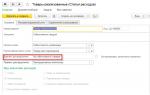
Black rectangle (below the text) with linear transparency effect in CorelDraw
People who work on websites have a more or less clear understanding of how Photoshop works, because the program is really convenient for pixel graphics, which are invisible on a good website. It is clear that webmasters do not use even a twentieth of all the capabilities of this powerful program, but they know exactly, for example, how to change the transparency of an image or a separate layer.
Things get more complicated if you have to work with vector graphics - usually designers deal with this and programs such as CorelDraw. And even then not all. But in Corel, setting the transparency of an element is as easy as shelling pears!
The word “Transparency” (Opacity) is hard to miss in the Photoshop layers panel, where the main work is done. All that remains is to move the slider where you need it - to decrease or increase the transparency of the layer (picture).

How to simply change the transparency of a picture in Corel is written and shown below.
A short CorelDraw lesson: Transparency
Interactive transparency in CorelDraw is one of the most important tools for achieving effects. Using this tool, you can create and change the transparency of objects: uniform, transitional (gradient) or textured.
Interactive transparency is located, by default, in the left panel of CorelDraw, an icon in the form of a glass. But usually the icon is hidden in a submenu of another icon - interactive form flow. You can open a submenu by long-clicking on the icon. Here's where transparency actually comes in:


It can be easily applied to an object. Simply click on the object with the mouse, drag the mouse slightly to the side and release. In this case, transparency will appear as a gradient (transition):

If you need uniform transparency, then after selecting the tool you just need to select the degree of transparency of the selected object:

The same thing in CorelDraw in Russian:

Marked in red is where to select the degree of transparency.
Other types of transparency can be selected in the menu at the top after selecting the tool:

The same thing in CorelDraw in Russian:

You can edit transparency in the form of linear, radial and other gradients using the button on the panel at the top, to the left of choosing the type of transparency.
Enlarging a raster image makes the scattered pixels within it visible. Tracing it, in addition to getting rid of pixels, will make it possible to work separately with each of the objects that will be contained in the resulting vector image. The quality of the drawing will be significantly higher. Let's look at how to make a vector image in Corel.
Ways to convert a raster drawing into a vector drawing in CorelDraw.
If you have a photograph as the source image, then rendering it in a vector will be problematic. This is usually done with designs, graphics, logos or similar things.
Scan (photo) - Import

Volume
To make the character look more interesting, he is given a play of chiaroscuro. This is usually done using Bezier.
Or you can do this: copy the hand twice, give the top copy a left offset, select both fragments, and activate the Back minus front command in the Property Bar. You will get a shadow, for which you need to choose a darker color than the main color. Creating highlights is similar, but is painted in a lighter color.

After playing with chiaroscuro, all that remains is to depict the falling shadow of the entire object. Using Ellipse, an oval is applied to the drawing. Drop Shadow creates a drop shadow, the characteristics of which are adjusted in the Property Bar.

Now you need to remove the oval. Open the Object Manager tool in Windows/Dockers, activate the oval-shadow group in the picture with the right mouse, select Break Drop Shadow. All that remains is to remove the unnecessary oval and place the shadow in the right place.

Automatic tracing
Although for some reason manual tracing is considered convenient by the majority, in practice the same majority uses automatic tracing. And this is understandable: it’s one thing to talk about work, and another thing to do it. There are several applications for this.
First, the bitmap is selected and the Trace Bitmap command is selected in the properties panel. Then a separately launched CorelTrace application window will provide the opportunity for further processing of the specified drawing.

Tracing is started with the To Trace command from the top menu. If the visible result in the work area (on the right) does not meet expectations, you can try to improve it qualitatively.
Play with the value in the Accuracy cell by moving the slider. This value determines the clarity of the trace. Please note that increasing it will lead to the creation of more vector objects (sometimes up to several thousand). And this will require additional processor power, memory (and/or time).

It is possible to select tracing methods using the buttons in the left section of the worksheet menu:
- For example, clicking Scetch and then activating Outline (above) will create a sketch of an abundance of intersecting lines.
- Selecting Advansed Outline will take you to advanced routing settings. Then additional fields will appear at the top to improve the adjustments.
After finishing working with a vector drawing, to return to CorelDraw, you need to exit CorelTrace using the File/Exit command. The work of the tracer will be completed, and the vector result will be transferred to Corel and placed above the raster one. To see it (raster) again, you need to move the newly created drawing to the side.
If the CorelTrace utility existed as a separate application, then PowerTrace is already built into CorelDraw X5.

Here the result of auto-routing is of quite decent quality.
It presents the following types (choice in the Type of image set):
- for black and white sketches - Line art;
- emblems, signs with a minimum of details and colors - Logo;
- emblems, signs with deep detail - Detailed logo;
- sketches with variable detail - Clipart;
- for photos with minor details - Low quality image;
- photo with important details - High quality image.
The Preview selection list allows you to select the most convenient version of the working window. The Before and After option will show both pictures at the same time to evaluate the differences. The number of points (nodes) and softening of curved lines is controlled by the Smoothing slider, detailing is controlled by Detail. The color scheme for the picture is determined by the Colors tab and the Color Mode set, and their number in the Numbers of colors cell.
Now you know how to draw a vector from an image in CorelDraw. Using this technology, professional compositions are obtained that can be used not only for personal purposes.
Leave your comments, ask questions, share your successes.